Steel Glossary
Hardox 600
| C*) | Si*) | Mn*) | P*) | S*) | Cr*) | Ni*) | Mo*) | B*) | |
|---|---|---|---|---|---|---|---|---|---|
| max. | 0.47 | 0.70 | 1.40 | 0.015 | 0.01 | 1.20 | 2.50 | 0.70 | 0.005 |
The steel is a fine-grain steel. *) Intended alloying elements.
| Hardox 600 is an extra-hard and tough wear-resistant steel for extreme wear conditions. | |||||||||||||||||
|---|---|---|---|---|---|---|---|---|---|---|---|---|---|---|---|---|---|
| Hardness (Guaranteed Value) |
HBW 570 - 640 (Thicknesses above 51mm: 550 - 640 HBW). The plates are through-hardened to at least 90% of the guaranteed minimum surface hardness. | ||||||||||||||||
| Heat Treatment | Hardox 600 is not intended for further heat treatment. The properties present in the delivery condition cannot be maintained if the steel is exposed to temperatures above 250°C. |
||||||||||||||||
| Delivery Condition | Hardened and tempered | ||||||||||||||||
| Surface | In accordance with EN 10163-2 Class A, Subclass 1 | ||||||||||||||||
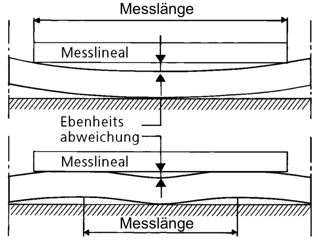
| Flatness |
Tolerances according to Hardox flatness guarantees, Class E, which are stricter than the tolerances of DIN EN 10029, Class N.
The values represent flatness, measured in mm over a 1-meter ruler. |
||||||||||||||||
| Weldability |
  |
||||||||||||||||
Ultrasonic Testing
Each sheet is extensively tested, certificates 3.1 are available, and internal standards are often stricter than the industry standard.
Surface Inspection1)
| According to EN 10 160 |
Distance between parallel test lines [mm] | Minimum error area to be considered [mm²] | Maximum allowable error area [mm²] | Maximum number of local errors [Number/m²] | Corresponding Steel-Iron Delivery Conditions |
|---|---|---|---|---|---|
| - | 100 | 1,000 | 10,000 | 1 | SEL 072 Class 5 |
| S0 | 100 | 1,000 | 5,000 | 20 | - |
| S1 | 100 | 100 | 1,000 | 15 | SEL 072 Class 3 |
| S2 | 50 | 50 | 100 | 10 | SEL 072 Class 2 |
| S3 | 50 | 20 | 50 | 10 | SEL 072 Class 1 |
Edge Zone Inspection2)
| According to EN 10 160 |
Edge Zone Width2) [mm] | Minimum Length of Defect to Consider [mm] | Maximum Length of Defect Allowed [mm] | Maximum Allowed Defect Area [mm²] | Maximum Number of Defects per Meter Length | Corresponding Steel-Iron Delivery Conditions |
|---|---|---|---|---|---|---|
| E0 | 50 - 100 | 50 | 100 | 2,000 | 6 | - |
| E1 | 50 - 100 | 25 | 50 | 1,000 | 5 | SEL 072 Klasse 3 |
| E2 | 50 - 100 | 20 | 40 | 500 | 4 | SEL 072 Klasse 2 |
| E3 | 50 - 100 | 15 | 30 | 100 | 3 | SEL 072 Klasse 1 |
| E4 | 50 - 100 | 10 | 20 | 50 | 2 | - |
1) The inspection can be ordered and performed as a comprehensive inspection, for example, E1S1 or E2S 2, or as edge zone-only or surface-only inspection, for example, E1 or S1.
2) The width of the edge zone in the edge zone inspection varies depending on the thickness of the sheet.
The thickness tolerances of the sheets according to AccuRollTech™ are tighter than DIN EN 10 029.
| Nominal Thickness [mm] | Hardox Tolerance Class A [mm] | Maximum Thickness Variation in the Sheet [mm] | |||
|---|---|---|---|---|---|
| min | max | ||||
| - | 4.9 | -0.3 | +0.4 | 0.5 | |
| 5.0 | - | 7.9 | -0.3 | +0.6 | 0.6 |
| 8.0 | - | 14.9 | -0.4 | +0.6 | 0.7 |
| 15.0 | - | 24.9 | -0.5 | +0.7 | 0.8 |
| 25.0 | - | 39.9 | -0.7 | +0.8 | 1.0 |
| 40.0 | - | 79.9 | -0.9 | +1.5 | 1.1 |
| 80 | - | -1.0 | +2.2 | 1.2 | |
Hardox sheets have an amazing flatness.
| 6.0 - 7.9 | 8.0 - 24.9 | 25.0 - 39.9 | 40.0 - 65.0 | ||
|---|---|---|---|---|---|
| Hardox 600 | Quarto-Sheet
Class E Measuring length 1,000mm |
11mm | 10mm | 9mm | 8mm |
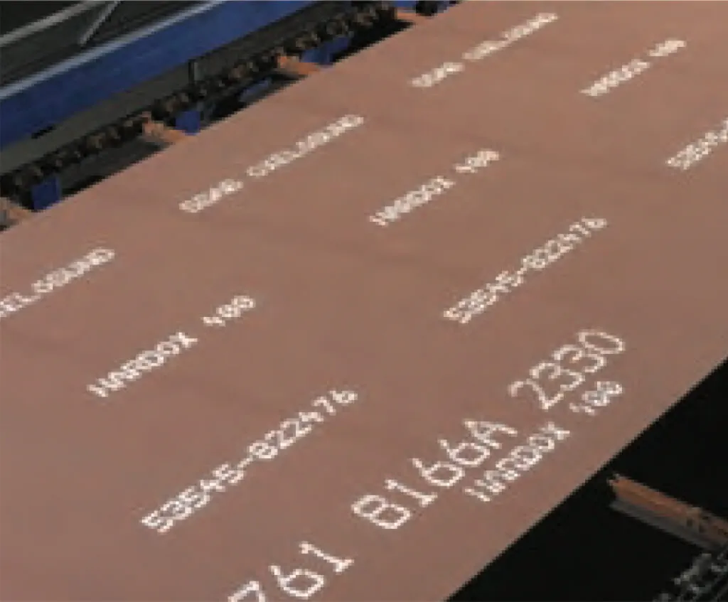
Sheets made of Hardox are equipped with a standard rust protection coating and an individual sheet identification.
Welding Instructions
Hardox combines unique wear resistance with excellent weldability. All common welding methods can be used for connections between Hardox and weldable steels.
For best welding results, pay attention to dryness, cleanliness, and freedom from corrosion. Special attention should be given to the selection of welding material, temperatures, heat input, and joint geometry.
Low-alloy or unalloyed welding materials with a tensile strength of 500 MPa are suitable for Hardox and Toolox. Hardox 450 in thicknesses from 0.7 to 6.0 mm allows materials with strengths of 900 MPa. Low-alloyed materials result in higher hardness, which benefits wear resistance. If the wear resistance of the weld is decisive, the addition of a wear-resistant overlay can be considered.
| Welding Process | DIN EN ISO Classification |
|---|---|
| MAG / Solid Wire | EN ISO 14341-A- G 38x EN ISO 14341-A- G 42x |
| MAG / Flux Cored Wire | EN ISO 17632-A- T 42xH5 EN ISO 17632-A- T 46xH5 |
| MAG / Metal Powder Flux Cored Wire | EN ISO 17632-A- T 42xH5 EN ISO 17632-A- T 46xH5 |
| MMA / Covered Electrode | EN ISO 2560-A E 42xH5 EN ISO 2560-A E 46xH5 |
| SAW / Submerged Arc Welding | EN ISO 14171-A- S 42x EN ISO 14171-A- S 46x |
| TIG / Tungsten inert gas welding | EN ISO 636-A- W 42x EN ISO 636-A- W 46x |
Low-alloy or unalloyed additions
Stainless welding additives can be used for all Hardox steels, and they are preferred for Toolox 44. They allow welding at 5 – 20°C without preheating, except for Hardox 600 and Hardox Extreme. SSAB recommends the following materials, which provide a yield strength of 500 MPa.
| Welding Process | DIN EN ISO Classification |
|---|---|
| MAG / Solid Wire | EN ISO 14343-A: B 18 8 Mn/ EN ISO 14343-B: SS307 |
| MAG / Flux Cored Wire | EN ISO 17633-A: T 18 8 Mn/ EN ISO 17633-B: TS307 |
| MAG / Metal Powder Flux Cored Wire | EN ISO 17633-A: T 18 8 Mn/ EN ISO 17633-B: TS307 |
| MMA / Covered Electrode | EN ISO 3581-A: 18 8 Mn/ EN ISO 3581-B: 307 |
| SAW Submerged Arc Welding | EN ISO 14343-A: B 18 8 Mn/ EN ISO 14343-B: SS307 |
| TIG | EN ISO 14343-A: W 18 8 Mn/ EN ISO 14343-B: SS307 |
austenitic additives
For Hardox welding, the same gases are generally used as for welding low-alloy or non-alloy steels.
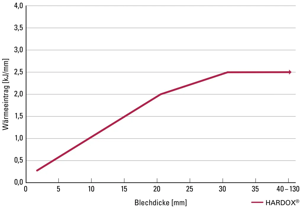
Recommended Maximum Heat Input

Hydrogen Content
The risk of hydrogen embrittlement is present for steels, and it can be mitigated by the following measures:
- Preheating the welding area
- Measuring the preheating temperature
- Using welding filler materials with a maximum of 5ml of water per 100g
- Keeping the welding joint free from rust, grease, oil, and cold temperatures
- Applying a suitable welding procedure
- Avoiding a welding gap over 3mm at the narrowest point of the joint
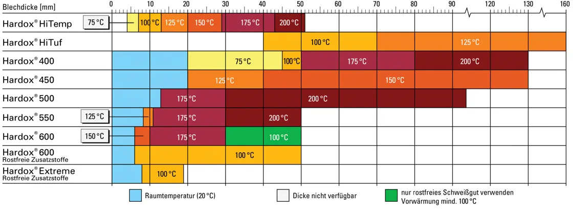
Preheating
Preheating is crucial for achieving a good weld joint. The recommended preheating temperatures for low-alloy
or non-alloy materials are shown in the following table.
Please note:
- For plates of different thicknesses, use the temperature for the thicker plate.
- For different plate materials, use the temperature of the material with the higher preheating temperature.
- For heat input below 1.7 kJ/mm, increase the temperature by 25°C; for heat input below 1.0 kJ/mm, consult the WearCalc program.
- In case of low ambient temperatures or high humidity, increase the temperature by 25°C.
- For DV or DY welds, start the first run outside the center of the plate.
Recommended Minimum Working Temperature
The maximum temperatures after welding one pass and before adding another pass are:
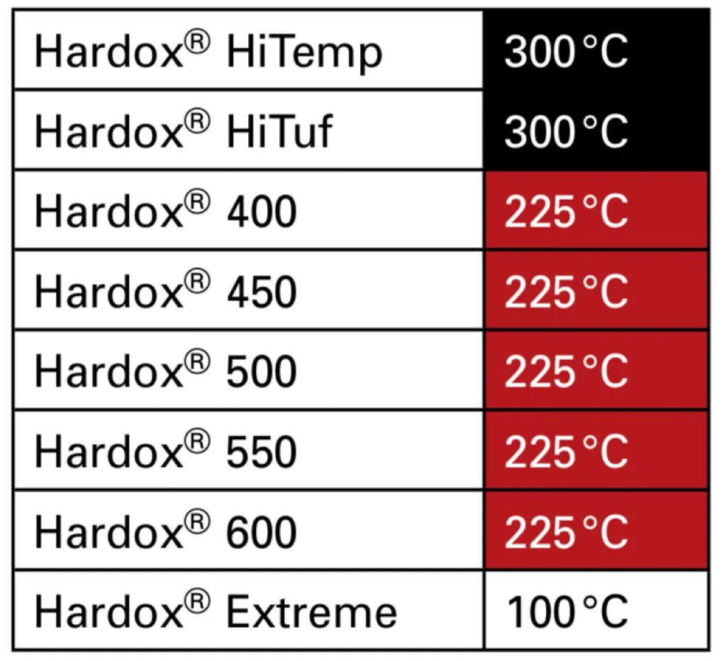
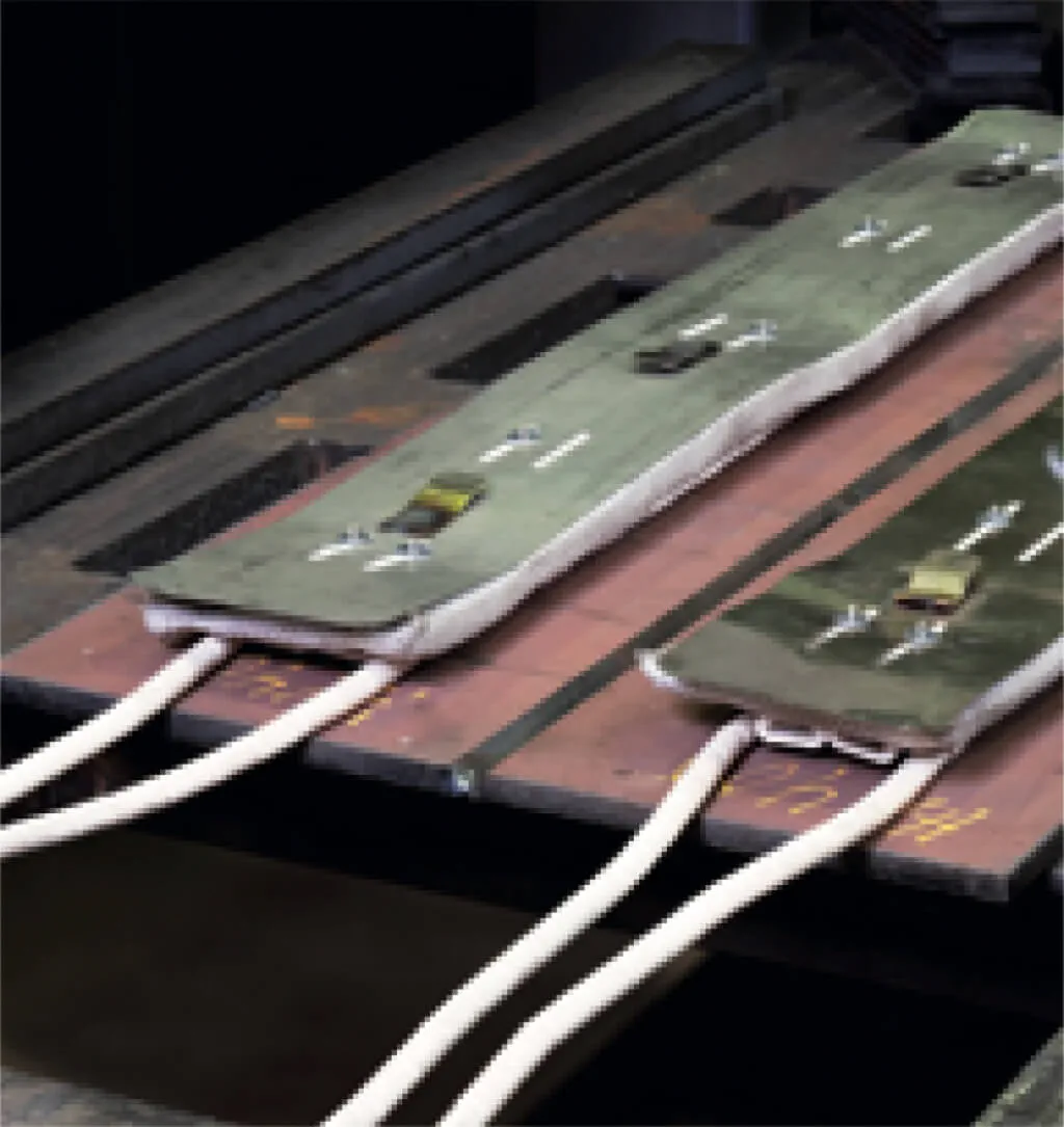
It is practical to measure the temperature on the backside.
It is recommended to wait about 2 minutes per 25mm plate thickness.
The temperature should be reached approximately 75 – 150mm on both sides of the weld joint.
Primed Plates
Due to the low zinc content, it is possible to weld directly on the Hardox primer. However, it is advantageous to remove the primer with a wire brush to avoid porosities. Good ventilation is important for the health of the welder and individuals nearby.
Heat Treatment
Heat treatment after welding is not recommended to preserve the mechanical properties of Hardox.
Hardness Comparison Table for Toolox and Hardox
| Tensile Strength MPa |
715 | 790 | 820 | 861 | 935 | 995 | 1,011 | 1,090 | 1,169 | 1,245 | 1,328 | 1,412 | 1,494 | 1,580 | 1,758 | 1,940 | 2,130 |
| Vickers Hardness HV |
205 | 233 | 243 | 261 | 289 | 311 | 317 | 345 | 373 | 401 | 429 | 458 | 485 | 514 | 569 | 627 | 682 |
| Brinell Hardness HBW |
225 | 250 | 260 | 275 | 300 | 320 | 325 | 350 | 375 | 400 | 425 | 450 | 475 | 500 | 550 | 600 | 650 |
| Rockwell HRC |
19 | 22.5 | 24 | 26 | 29 | 32 | 32.5 | 35.5 | 38 | 40 | 42.5 | 44.5 | 46.5 | 49 | 52.5 | 55 | 57.5 |
Attention please!
Some features of our webshop are not supported by your current browser version.
We recommend updating your browser or using a different browser.

