Steel Glossary
Toolox 33
| C | Si | Mn | P | S | Cr | Mo | V | Ni | |
|---|---|---|---|---|---|---|---|---|---|
| Max. | 0.24% | 1.1% | 0.8% | 0.01% | 0.003% | 1.2% | 0.3% | 0.11% | 1.0% |
| Min. | 0.22% | 0.6% | - | - | - | 1.0% | - | 0.10% | - |
Toolox 33 is a hardened and tempered tool steel designed to have minimal residual stresses, resulting in excellent dimensional stability during machining. This material combines very good machinability with a hardness of 300 HBW. It is specifically intended for use in plastic molds and is highly suitable for polishing and etching.
Other applications of Toolox 33 include rubber molds, bending tools, wear parts, and structural components in mechanical engineering.
| Toolox 33 replaces materials 1.2311 / 1.2312 / 1.2738 / 1.7225 and unhardened 1.2842. | ||
|---|---|---|
| Hardness (Guaranteed Value) |
HBW 275 - 325 (equivalent to approximately 26 - 32.5 HRC) | |
| Impact Toughness (Guaranteed Value) |
Test Temperature 20°C |
Impact Toughness Charpy-V at transverse direction ≤ 130mm min. 35 J |
| Tensile Strength (Converted Value) |
Tensile Strength approximately 860 - 1,010 MPa | |
| Ultrasonic Testing (Guaranteed Value) |
According to EN 10 160 (plates) or EN 10 228-3 (forged parts) and additional requirements as per SSAB V6. | |
| Etching Properties (Warranty Obligation) |
Toolox 33 meets the requirements according to NADCA 207–2006. | |
| Dimensions | Toolox 33 is supplied in sheet thicknesses of 6 - 130mm. | |
| Delivery Condition | Hardened and tempered at a minimum of 590°C. | |
| Heat Treatment | Nitriding or coating is possible at temperatures below 590°C. Toolox 33 is not intended for further heat treatment. If this material undergoes further heat treatment above 590°C after delivery, the properties are no longer guaranteed. | |
| Testing | Testing according to EN 10 025 and EN ISO 6506-1. Hardness tested on a milled surface 0.5 - 2mm below the sheet surface. | |
| Tolerances | Sheet: According to EN 10 029 and SSAB AccuRollTech™. Round steel: EN 10 060 |
|
| Products | Precision flat steel (standard and special dimensions), EcoPlan, P-Plates, VarioPlan and raw material blanks. Machine parts and guide rails made to your specifications and drawings. | |
Metallurgical Information
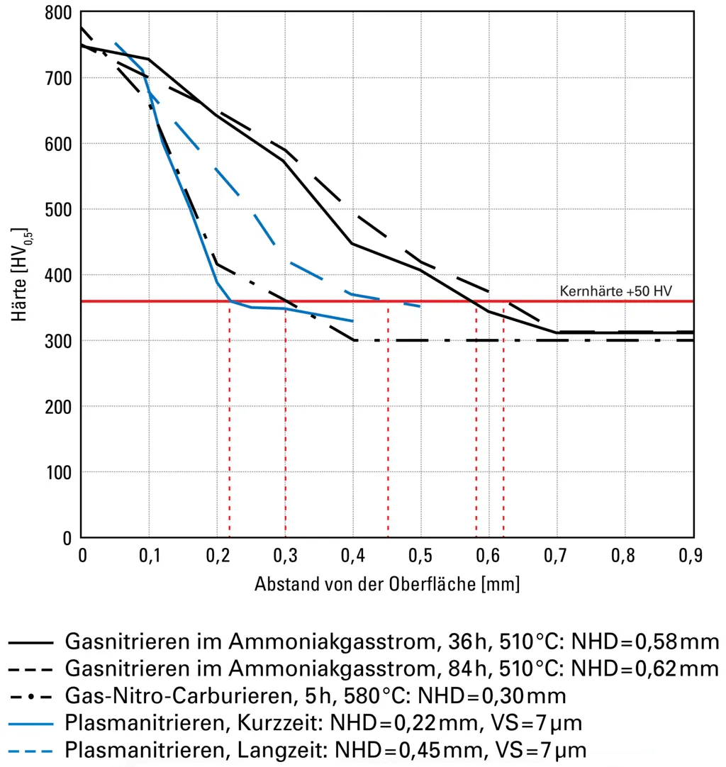
Hardness Profile
Nitriding Depth (NHD) according to DIN 50190-3 at core hardness +50 HV
Inclusions Content (Typical Values)
| Inclusion Rate (Equivalent Diameter) | 6 μm |
| Area Fraction | 0.015% |
| Length-Width Ratio | 1.2 |
Physical Properties (Typical Values)
| Thermal Expansion Coefficient [10^-6/K] | +20 – 200°C: 13.1 | ||||||
| Thermal Conductivity [W/mK] |
|
Short-Term
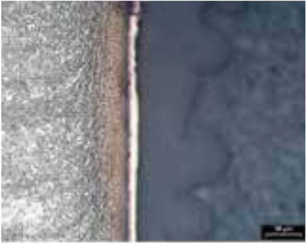
Diffusion zone, no compound layer
Long-Term
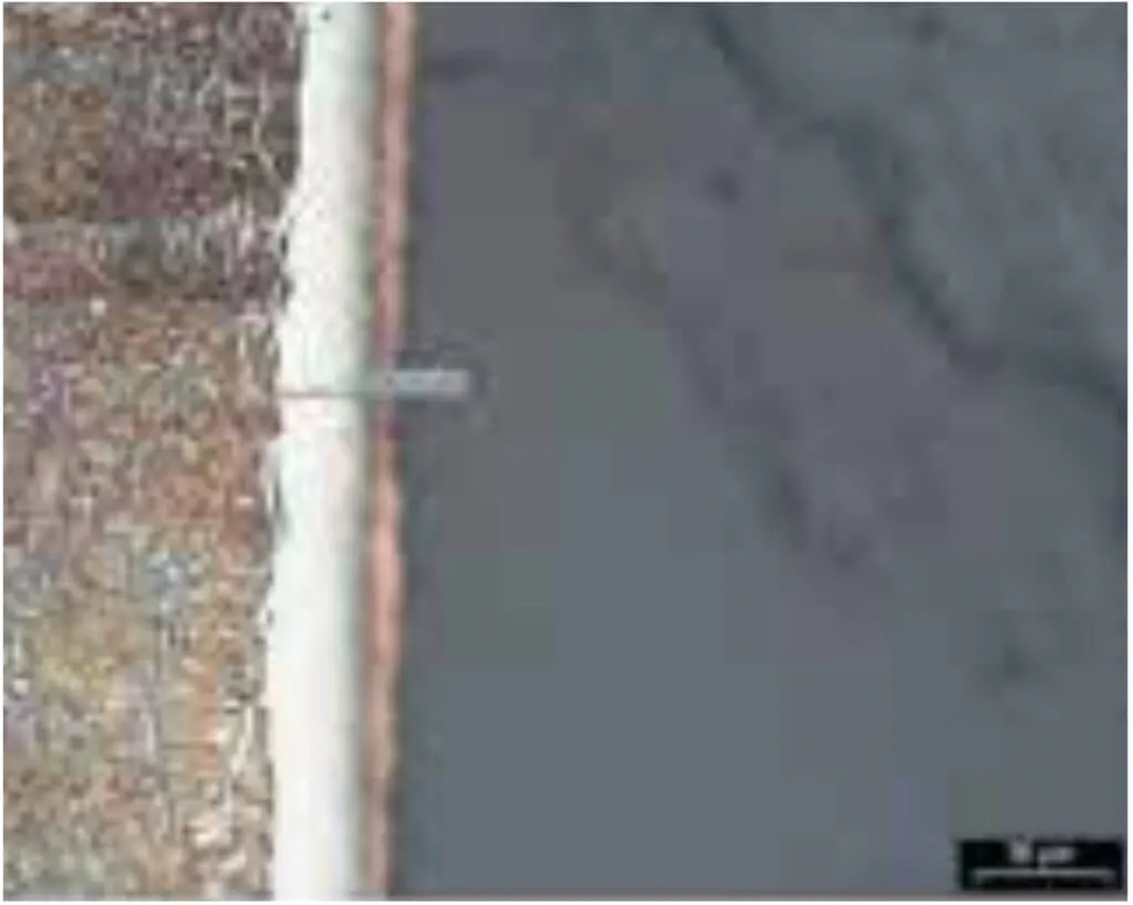
Diffusion zone, compound layer 36 μm
Surface Technology
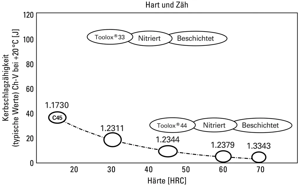
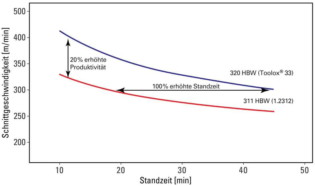
Tool Life in Face Milling
Mechanical Properties (typical values*)
| Guaranteed Hardness [HBW] | Guaranteed Charpy Impact Toughness Min [J] | Typical Charpy Impact Toughness [J]* | Typical Yield Strength Rp0.2 [MPa]* | Typical Tensile Strength Rm [MPa]* | Typical Elongation As [%]* | Typical Compressive Yield Strength [MPa]* | Thickness [mm] | |
|---|---|---|---|---|---|---|---|---|
| -40°C | 27 | 6 - 130 | ||||||
| -20°C | 45 | |||||||
| +20°C | 275 - 325 | 35 | 100 | 850 | 980 | 16 | 800 | |
| +200°C | 170 | 800 | 900 | 12 | 750 | |||
| +300°C | 180 | 700 | ||||||
| +400°C | 180 | 590 | ||||||
| +500°C | 560 |
Toolox is tested for hardness and Charpy impact toughness at room temperature.
All other values provided are from supplementary tests and are for information purposes only, but not guaranteed.
* Approximate values for informational purposes only.
Ultrasound Testing
Each sheet is extensively tested, and 3.1 certificates are available. Internal standards are often more stringent than the industry standard.
Surface Inspection1)
| According to EN 10 160 | Distance between parallel test lines [mm] | Minimum error area to be considered [mm²] | Maximum permissible error area [mm²] | Maximum number of local errors [number/m²] | Corresponding steel delivery conditions |
|---|---|---|---|---|---|
| - | 100 | 1,000 | 10,000 | 1 | SEL 072 Class 5 |
| S0 | 100 | 1,000 | 5,000 | 20 | - |
| S1 | 100 | 100 | 1,000 | 15 | SEL 072 Class 3 |
| S2 | 50 | 50 | 100 | 10 | SEL 072 Class 2 |
| S3 | 50 | 20 | 50 | 10 | SEL 072 Class 1 |
Edge zone inspection2)
| According to EN 10 160 |
Edge zone width2) [mm] | Minimum defect length to consider [mm] | Maximum permissible defect length [mm] | Maximum permissible defect area [mm²] | Maximum number of defects per meter length | Corresponding steel-iron delivery conditions |
|---|---|---|---|---|---|---|
| E0 | 50 - 100 | 50 | 100 | 2000 | 6 | - |
| E1 | 50 - 100 | 25 | 50 | 1000 | 5 | SEL 072 Class 3 |
| E2 | 50 - 100 | 20 | 40 | 500 | 4 | SEL 072 Class 2 |
| E3 | 50 - 100 | 15 | 30 | 100 | 3 | SEL 072 Class 1 |
| E4 | 50 - 100 | 10 | 20 | 50 | 2 | - |
1) The inspection can be ordered and performed as a complete inspection, for example, E1S1 or E2S2 , or as edge zone or surface-only inspection, for example, E1 or S1.
2) The width of the edge zone in the edge zone inspection varies depending on the thickness of the sheet.
The Thickness Tolerances of the sheets according to AccuRollTech™ are tighter than DIN EN 10 029.
| Nominal Thickness [mm] | Toolox Tolerance Class C [mm] | Maximum Thickness Variation in Sheet [mm] | |||
|---|---|---|---|---|---|
| min | max | ||||
| - | 4.9 | -0.0 | +0.7 | 0.5 | |
| 5.0 | - | 7.9 | -0.0 | +0.8 | 0.6 |
| 8.0 | - | 14.9 | -0.0 | +1.0 | 0.7 |
| 15.0 | - | 24.9 | -0.0 | +1.2 | 0.8 |
| 25.0 | - | 39.9 | -0.0 | +1.5 | 1.0 |
| 40.0 | - | 79.9 | -0.0 | +2.4 | 1.1 |
| 80 | - | -0.0 | +3.2 | 1.2 | |
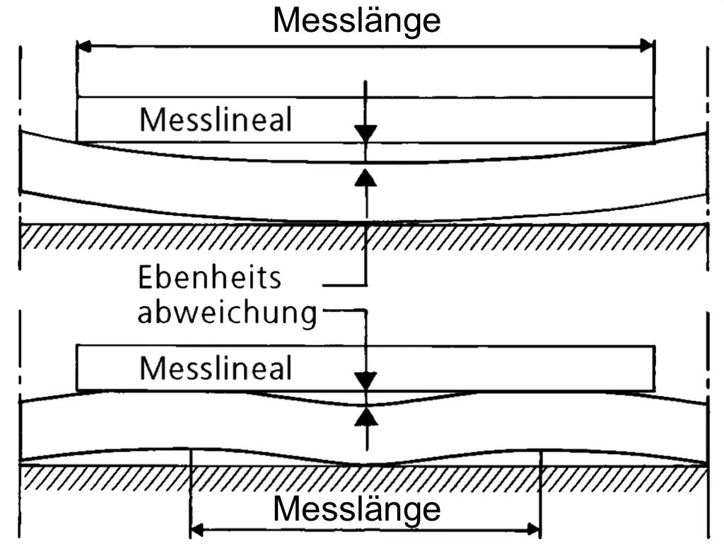
Toolox sheets have an astonishing flatness.
| 5.0-7.9 | 8.0-14.9 | 15.0-24.9 | 25.0-99.9 | 100.0-155.0 | ||
|---|---|---|---|---|---|---|
| Toolox 33 | Quarto-Sheet Class S Measuring Length 1,000mm |
4mm | 3mm | 3mm | 3mm | 4mm |
| Quarto-Sheet Class S Measuring Length 2,000mm |
8mm | 6mm | 6mm | 6mm | 8mm | |
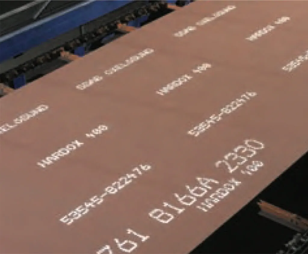
Toolox sheets come with a standard rust protection coating and individual sheet identification.
Processing of Toolox
All significant tool manufacturers are prepared for processing Toolox. It is advisable to seek advice on suitable tools and cutting data. These recommendations should be followed in a textbook-like manner to achieve optimal results and productive performance. It is essential to avoid reducing the feed rate out of misguided caution. Good chip formation leads to success, and Toolox rewards you with long tool life and faster processing.
Drilling
Drilling with HSS tools is reserved for less stable machines and low quantities. HSS-Co tools with the cutting data provided below have proven to be effective. Pay attention to continuous machine feed and sharp tools. A pointed cross edge would be advantageous to ensure optimal chip formation.
| Toolox 33 | |
|---|---|
| Speed: v [m/min] | ~ 15 |
| Diameter [mm] | Feed: f [mm/U] / Speed [1/min] |
| 5 | 0.10/950 |
| 10 | 0.10/475 |
| 15 | 0.16/325 |
| 20 | 0.23/235 |
| 25 | 0.30/195 |
| 30 | 0.35/165 |
| *35 | 0.40/136 |
| *40 | 0.45/119 |
Drilling with solid carbide tools is productive and efficient. It is recommended to use internal coolant with a higher concentration. Make sure to drill with continuous feed (not lower than the tool manufacturer's recommendation).
| Toolox 33 | ||
|---|---|---|
| Speed: v [m/min] | 65–90 | |
| Diameter [mm] | Feed [mm/U] | |
| min.-max. | Starting Value | |
| 3.0 – 5.0 | 0.08 – 0.15 | 0.10 |
| 5.01 – 10.0 | 0.09 – 0.16 | 0.12 |
| 10.01 – 15.0 | 0.16 – 0.22 | 0.18 |
| 15.01 – 20.0 | 0.22 – 0.28 | 0.25 |
Replaceable solid carbide heads or brazed inserts are used for medium diameters. Refer to the table for cutting values.
| Toolox 33 | ||
|---|---|---|
| Speed: v [m/min] | 50-80 | |
| Diameter [mm] | Feed [mm/U] | |
| min.-max. | Starting Value | |
| 7.5 – 12.0 | 0.10–0.16 | 0.13 |
| 12.01 – 20.0 | 0.15–0.23 | 0.20 |
| 20.01 – 25.0 | 0.18–0.27 | 0.22 |
| 25.01 – 30.0 | 0.20–0.30 | 0.24 |
Long holes up to over 50 x D can also be produced very productively on machining centers with IKZ (internal coolant supply) by using solid carbide drills with a special geometry. The table below shows typical cutting values.
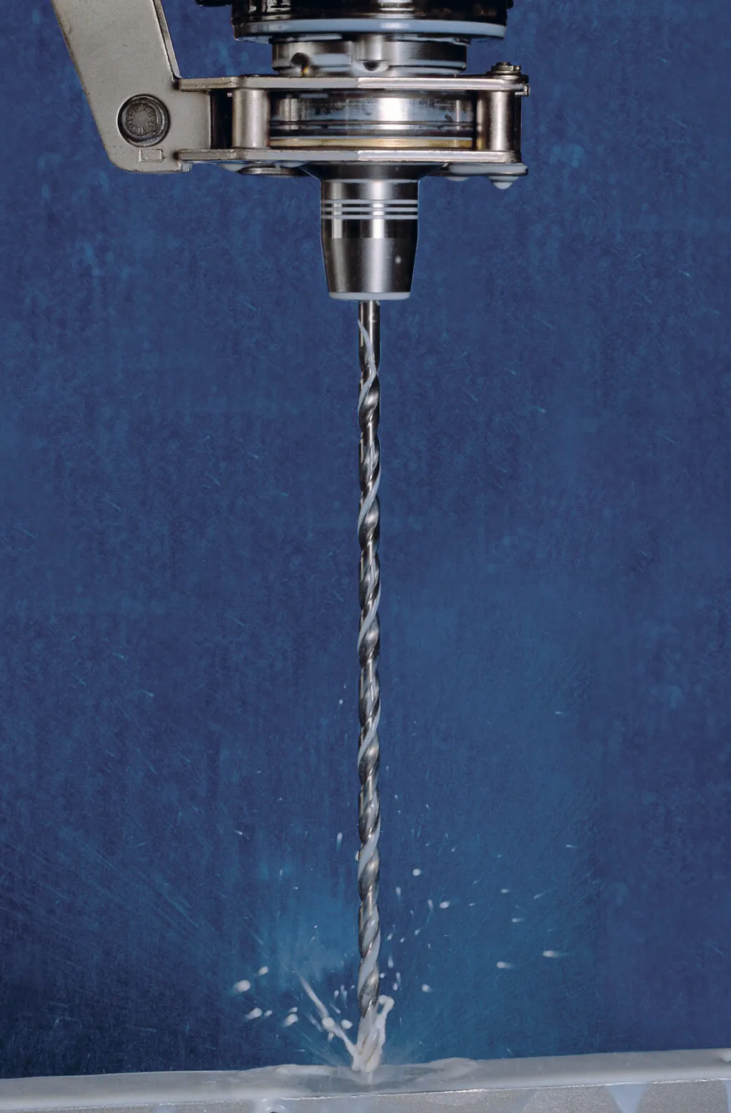
| Material | Hardness | Dia. | Depth | Rel. Depth | Cutting Data | Coolant | ||
|---|---|---|---|---|---|---|---|---|
| d [mm] | l [mm] | l/d | vc [m/min] | f [mm] | vf [mm/min] | Emulsion | ||
| Toolox 33 | 300 HB | 5 | 10 | 20 | 50 | 0.15 | 477 | IK, p=20bar |
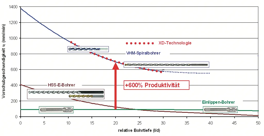
Deep Drilling in Toolox presents a special challenge, which the renowned manufacturer Botek masters and solves economically with a special cutting edge geometry. The single-lip solid drilling tools Type 110 with special geometry for diameters up to 12.0mm, as well as single-lip deep drilling tools Type 01 with interchangeable cutting inserts and guide pads in special design from diameter 12.0mm, have proven to be excellent solutions.
For further information, please contact Botek Company and feel free to refer to us.
| Drill Diameter [mm] | 3 | 4 | 5 | 6 | 7-8 | 9-10 | 11-12 | >12 |
|---|---|---|---|---|---|---|---|---|
| Cutting Speed [m/min] | 50 | 50 | 50 | 50 | 40-50 | 40-50 | 40-50 | 40-50 |
| Feed Rate [mm/U] | 0.005 | 0.01 | 0.015 | 0.0175 | 0.02 | 0.03 | 0.04 | 0.1 |
| Coolant Pressure [bar] | 100 | 100 | 100 | 90 | 80 | 70 | 60 | 40 |
| Center Drilling Distance [mm] | 40 | 40 | 50 | 60 | 60 | 70 | 70 | 70 |
| Center Drilling Feed [mm/U] | 0.0025 | 0.005 | 0.0075 | 0.009 | 0.01 | 0.015 | 0.02 | 0.05 |
Achievable tool life with oil: approx. 10 – 12 meters under optimal process conditions.
Miling
Toolox is particularly resistant to distortion due to extremely low residual stresses when machined with optimal parameters and without introducing unnecessary heat into the workpiece. Long tool life is achieved through clever milling strategies, stable clamping, and sufficient chip thickness. Toolox has a unique microstructure that facilitates machining despite its high hardness. The carbides in Toolox are very hard and wear-resistant microstructure components. Their microscopically fine, spherical form in the Toolox microstructure prevents the cutting edge damage typical in other tool steels. Sufficiently high tooth feed ensures the removal of the carbides along with the chip, while too low a feed would lead to intense abrasive wear on the cutting edge. Sharp cutting edges with positive geometry are optimal for machining Toolox. Choose tools specifically designed for machining high-alloyed steels. Tools for hard machining (up to 60 HRC) are unsuitable, as their cutting edges typically have negative rake angles.
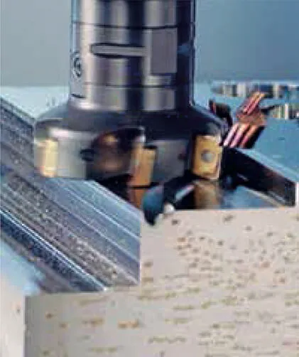
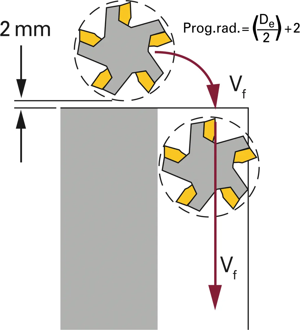
Entry using "Roll-In" method
Wear after 800 passes
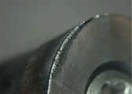
Straight entry into the workpiece
Wear after 390 passes
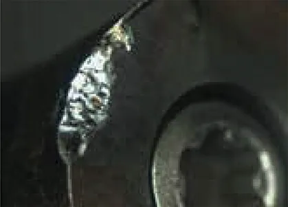
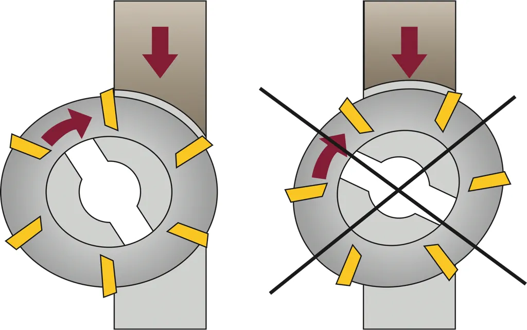
Introduction to the cutting process using the 'roll-in' method
Face Milling
Interrupted cuts are better milled with round inserts. Particularly high productivity can be achieved with HPC tools. Also, face mills are suitable for Toolox.
Recommendation for 45° cutters
| Toolox 33 | ||
|---|---|---|
| Cutting speed: v [m/min] | 180-220 | |
| Feed rate: fz [mm/tooth] | min. – max. | Starting value |
| Insert grade P30 | 0.15–0.35 | 0.25 |
Recommendation for face milling cutters with round inserts
| Toolox 33 | ||
|---|---|---|
| Cutting speed: v [m/min] | 180-220 | |
| Feed rate: fz [mm/tooth] | min. – max. | Starting value |
| Insert grade P30 | 0.10–0.25 | 0.15 |
Recommendation for face mills / face milling heads
| Toolox 33 | ||
|---|---|---|
| Cutting speed: v [m/min] | 180-220 | |
| Feed rate: fz [mm/tooth] | min. – max. | Starting value |
| Insert grade P30 | 0.12–0.25 | 0.17 |
Cutting values for HPC copy and face mills
| Material group | Material designation | Strength N/mm2 | Copy Milling | Plunge / Boring Circular Milling | ||||||||||||||
|---|---|---|---|---|---|---|---|---|---|---|---|---|---|---|---|---|---|---|
| Dry Machining | Wet Machining | Dry Machining | Wet Machining | |||||||||||||||
| Preferred Cutting Material | Vc [m/min] | Preferred Cutting Material | Vc [m/min] | Preferred Cutting Material | Vc [m/min] | Preferred Cutting Material | Vc [m/min] | |||||||||||
| Min | Start | Max | Min | Start | Max | Min | Start | Max | Min | Start | Max | |||||||
| 8.2 | Toolox 33 Tool steels |
900–1100 | F25M | 120 | 140 | 160 | F25M | 110 | 130 | 150 | F25M | 80 | 90 | 100 | F25M | 70 | 85 | 100 |
End Milling
For slot milling, a depth per pass (ap) of 0.5 x D has proven to be effective, and sufficient chip space should be available. End milling, including trochoidal milling, is very productive with full cutting length ap and a feed per tooth (ae) of about 0.1 x D. Dry milling with compressed air cooling to remove chips helps avoid thermal shock and overload due to trapped chips.
Thread Milling
strong Both Toolox materials can be machined with machine taps. Experienced locksmiths often drill a slightly larger pilot hole. Cutting paste, cutting oil, or a richer emulsion have proven to be particularly effective.
| Toolox 33 | |
|---|---|
| Cutting speed: v [m/min] |
7-10 |
| Size | Speed [1/min] |
| M5 | 445–635 |
| M6 | 370–530 |
| M8 | 270–400 |
| M10 | 220–320 |
| M12 | 185–265 |
| M16 | 140–200 |
| M20 | 110–160 |
Thread milling is a productive method that offers high manufacturing reliability, especially for very small diameters and in situations where thread cutting is difficult.
| Toolox 33 | |
|---|---|
| Cutting speed: v [m/min] |
80-110 |
| Feed rate: fz [mm/tooth] | 0.03 – 0.06 |
Countersinking and Chamfering
Countersinking as well as chamfering can be easily achieved on machining centers using indexable insert tools. For less stable machines, countersinks with revolving centering pins have proven to be effective.
| Toolox 33 | |
|---|---|
| Cutting speed: v [m/min] |
0.10-0.20 |
| Diameter [mm] | Speed [1/min] |
| 19 | 670–1340 |
| 24 | 530–1060 |
| 34 | 375–750 |
| 42 | 300–600 |
| 57 | 225–440 |
Polishing Toolox
- Fine grinding with coarse abrasive (e.g., grit size 120). Completely remove all traces of processing or eroding. Preferably, use the flat side of the abrasive to achieve an absolutely flat surface. Vary the grinding direction in an X-pattern to create an efficient and time-saving process while obtaining a flat surface.
- Repeat the fine grinding process from Step 1, but with a finer grit size, such as 320. Completely eliminate any remaining traces from the previous grinding.
- Rough polishing with diamond paste on a piece of brass. Use a grit size of 45μm. Perform this rough polishing until all remaining traces and scratches from the previous step (Step 2) are completely removed.
- Repeat the process from Step 3, but now with 15μm diamond paste, until all traces remaining from Step 3 are gone.
- Proceed as in Step 4, but use a 7μm diamond paste. Continue this step until all traces from Step 4 are removed.
- Polish with 7μm diamond paste on a fiber or plastic element. Continue until the last remaining irregularities from Step 5 are eliminated.
- Proceed as in Step 6, but use a 3μm diamond paste instead of 7μm. Continue until the last subtle nuances of irregularities from Step 6 are removed. (We use the word "nuance" here because at this point, the surface is already so flat and fine that there are no visible scratches to the naked eye.)
- Polish with 3μm diamond paste on a piece of felt until all remaining nuances from the previous step are gone.
- As a final step, polish with 3μm diamond paste and cotton. This is a manual process to achieve the final shine. Continue until the entire surface exhibits a uniform shine.

Welding of Toolox
Toolox is well weldable if the following instructions are observed. The carbon equivalent for Toolox 33
is CEIIW 0.62–0.71 / CET 0.4–0.44.
Suitable austenitic welding fillers for welding without preheating are AWS 307 or AWS 309. The
strength achieved in the weld is approximately Rp0.2 = 500 MPa.
Non-alloyed or low-alloyed welding fillers can achieve strengths of up to approximately Rp0.2
= 930 MPa and provide good toughness.
- Preheat both sides of the weld joint, approximately 100 – 150mm on each side. The preheating temperature should be reached at the center of the plate. Maintain the preheating temperature throughout the entire welding process, especially during tack welding.
- Use soft or stainless electrodes if possible. The electrodes must be dry. The maximum allowable hydrogen content is 5ml/100g of the welding material. To achieve optimal texture formation, welding should be done using the TIG process with a filler wire having the same chemical composition as the base material. The simplest method is to cut a rod from a leftover piece of the base material.
- Weld with a heat input resulting in a Δt8/5 value between 10 and 20s.
- Before welding the next layer, the interpass temperature for Toolox 33 should not exceed *170°C.
- Perform a post-weld heat treatment in the area of approximately 100 – 150mm on each side of the weld joint. The holding time should be 5 min / mm of plate thickness or at least 60 minutes. Normally, a holding time of 2 hours is sufficient. The start of the holding time is the point at which the temperature is uniform throughout the tempering volume.
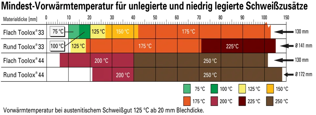
* Post-weld heat treatment should be performed at a temperature of 150 – 200 °C if only low requirements for dimensional stability are needed.
* Post-weld heat treatment should be performed at a temperature of 560 – 580°C if high requirements for dimensional stability are needed, and the influence of the weld on the texture formation result should be minimized.
Hardness Comparison Table for Toolox and Hardox
| Tensile Strength MPa |
715 | 790 | 820 | 861 | 935 | 995 | 1011 | 1090 | 1169 | 1245 | 1328 | 1412 | 1494 | 1580 | 1758 | 1940 | 2130 |
| Vickers Hardness HV |
205 | 233 | 243 | 261 | 289 | 311 | 317 | 345 | 373 | 401 | 429 | 458 | 485 | 514 | 569 | 627 | 682 |
| Brinell Hardness HBW |
225 | 250 | 260 | 275 | 300 | 320 | 325 | 350 | 375 | 400 | 425 | 450 | 475 | 500 | 550 | 600 | 650 |
| Rockwell HRC |
19 | 22.5 | 24 | 26 | 29 | 32 | 32.5 | 35.5 | 38 | 40 | 42.5 | 44.5 | 46.5 | 49 | 52.5 | 55 | 57.5 |
Attention please!
Some features of our webshop are not supported by your current browser version.
We recommend updating your browser or using a different browser.

